-
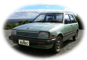
When selecting your 'Donor" car choose one which is
structurally sound with little or no rust.
-
Choose a lighter car as possible to keep the power
requirements as low as possible eg. motor size and battery capacity.
-
If you must place holes in the floor or any part of
the car body, ensure that these do not weaken the vehicle's structural
strength. If holes are near seat or seat belt mountings, they could
weaken these mounting points and cause some of the Australian Design
Rules (ADR's) to fail on examination.
-
If using lead acid batteries the weight of the
batteries should be at least 30% of the vehicle's GVM (Gross Vehicle
Mass).
-
Get hold of the book by Bob Brant and Seth Leitman, "Build Your Own
Electric Vehicle" - 3rd Edition. This book (352 pages) has a wealth of information
about all aspects of vehicle conversion, EV history, batteries, motors,
controllers, EV examples etc. The best place to get this book is from
www.biblio.com.
Prices start from a few dollars for second hand books. Also available from
eBay or
Amazon This book (352 pages) has a wealth of information
about all aspects of vehicle conversion, EV history, batteries, motors,
controllers, EV examples etc. The best place to get this book is from
www.biblio.com.
Prices start from a few dollars for second hand books. Also available from
eBay or
Amazon
Make
sure you get the latest edition - like the one shown on the right...
Publication Date: January
29, 2013 |
ISBN-10: 0071770569 |
ISBN-13: 978-0071770569 |
Edition: 3
-
See the links at the bottom of the
What Car? page for car specification websites.
-
Batteries recommended are: Lithium Iron Phosphate
(LiFePO4).
Available in Australia from
EV-Works who
also supply the BMS to suit.
To visit
the website of the manufacturer:
Winston Battery Ltd.
-
The book "Convert
It!" by Michael P. Brown is available from various outlets and
I have
found this book to be very good, but a little dated.
-
Hook up with a local Electric Vehicle club - eg. in
Australia there is the
Australian Electric Vehicle Association.
Join in and gain knowledge
by
associating with experienced people who may be able to answer your
questions.
-
Purchase the DVD "Who
Killed The Electric Car?" from the Plug In America
website
for $US10.00 plus post.

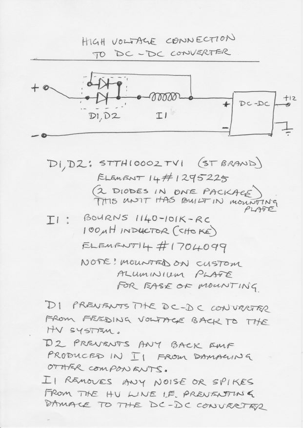
Protecting the DC-DC Converter
from System Power Drain
See
PDF or image below for
explanation.
This idea came from Jack Rickard (EVTV)
after many failures of his DC-DC Converters.
The secret of the whole circuit...
The series diode (D1) prevents the
DC-DC converter from supplying power to the rest of the system as the
pack voltage droops under sudden load eg. acceleration.
Eric
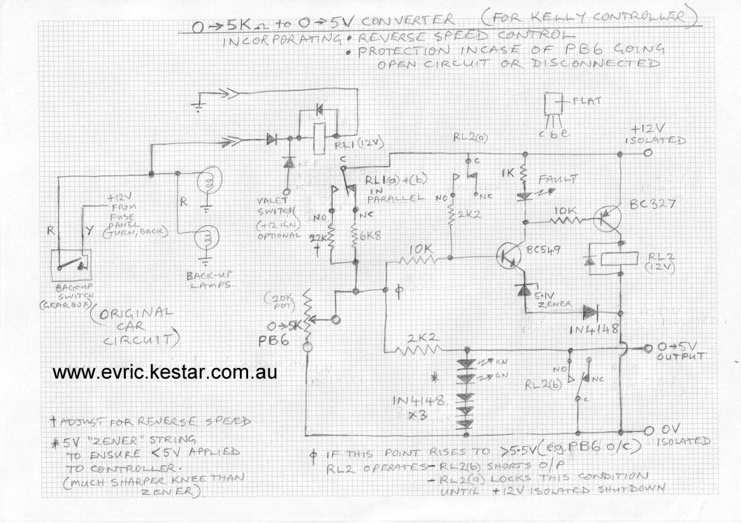
Using a PB-6 Pot Box with a Kelly Controller.
This is normally a difficult situation. Some say to open the PB-6
throttle pot box and connect to the third terminal of the pot. If this
is done the controller will work with the PB-6 except that the
top speed of the vehicle will be limited to under a third of the speed
that would normally be available. This is because of the fact that the
pot inside the PB-6 is in fact 20K ohm and not 5K ohm. Because of the
limited movement of the actuating arm the pot wiper travels over only 5K
ohms of the full value.
I have developed a circuit which will convert the 0-5K ohm from the
standard PB-6 (2 wires) to 0-5V to suit the Kelly controller.
I have incorporated two additional features as well:-
-
One is the reverse
speed control making use of the reversing switch in the gearbox. This
operates a relay and limits the output voltage to much less than 5V. An
optional valet switch is also included.
-
The
second feature is protection against having 5V applied to the controller
in the case of the pot box going open circuit or being partly disconnected,
which would normally be full throttle!. This uses a voltage sensing
circuit and another relay to reduce the output to 0 volts if this
happens. This can only be reset by turning the car off and on again.
In actual fact the output from the circuit I built is
0 - 4.65V but this is close enough as the Kelly setup allows for this in
the configuration program.
The 0-5V circuit is powered from a 12V isolated supply which
I use to power
the Kelly controller internal circuitry. I have included the circuit in
JPG (190Kb) and
PDF format (2.7Mb).
There are more notes on the actual circuit to explain some of the
component choices. This is a hand drawn circuit only - no excuses.
NOTE: I
take no responsibility for the resultant construction by any other
person.
PS. Someone claims that the true Curtis brand PB-6
pot box actually has a reduced travel (40 degrees ?)
5 K ohm pot inside. If someone could verify this
I would be pleased. If this is the case all three
terminals could be used as a potentiometer to
produce the 0-5V output. It will still work in the
circuit below with two terminals to take
advantage of the open circuit protection.
0-5K Ohm to 0-5Volt converter (Reduced
JPG version)
(Updated 14 March 2009)
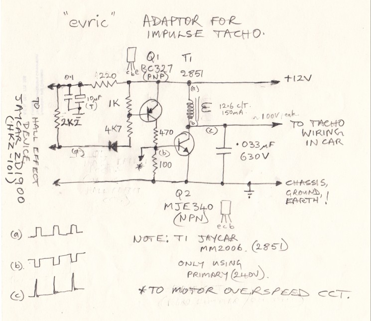
Using the Standard Tacho in an Electric Car.
I found a circuit on the the net, shown in an
article in Silicon Chip (Australia) magazine September 1997, page 30
and 31, and have
modified it to work between a Hall Effect pickup and the original standard
tachometer which did rely on high voltage pulses from the original
engine ignition coil
terminal.
The circuit presented here supplies those high voltage
pulses required by the tacho.
Available as
PDF.
For an original 4 cylinder (4 stroke) engine you need a
soft iron (steel) disk with 2 slots, each slot at least longer than the
width of the Hall Effect unit (approx 20mm or 3/4inch) evenly spaced.
For a 6 cylinder: 3 slots ...etc..
The Hall Effect device that I used was from Jaycar:
ZD1900 which is a
HKZ-101
or similar.
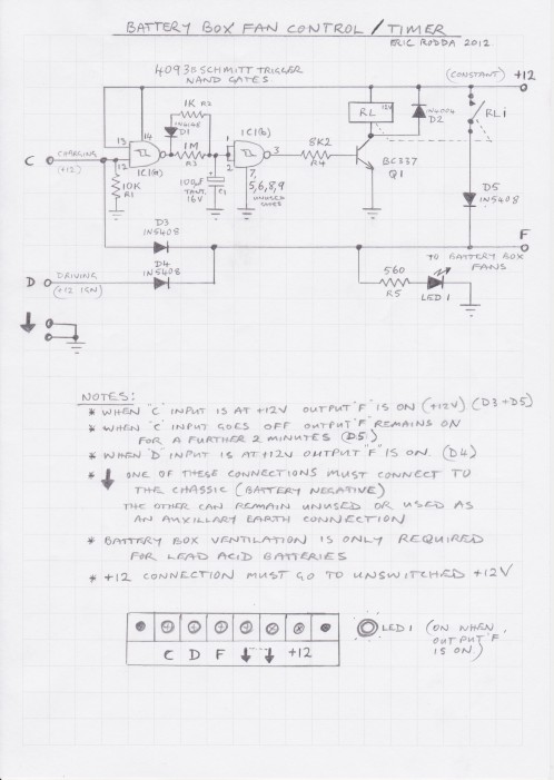
Design for Lead Acid Battery Box Control/Timer.
Please note that this was designed for use with Lead
Acid batteries mounted within the vehicle cabin.
...it was obviously not
used in the EVRIC EV (which is Lithium Iron Phosphate powered).
Please use/modify the design as you wish. The circuit
presumes that you have a +12Volt signal available when the batteries are
being charged (C).
NOTE: I take no responsibility for your construction of this design.
The Australian regulations for charging Lead Acid
batteries, which are in the cabin of the car, requires the installation
of sealed/vented battery boxes with fan forced ventilation. Part of the
requirement is that the fans stay on for a period after the charging is
completed or turned off. (Input C)
The regulation also requires the fan(s) to be running while the car is
being driven. (Input D)
This design allows the fan(s) (F) to remain on for 2
minutes after the charging circuit has been turned off.
This ensures that any gasses present are removed from the battery box.
The 2 minutes may have to be varied depending on the size of you battery
box and the air movement of the fan(s).
This unit was designed on a PCB which fitted into a
JAYCAR box
HB6014,(130 x 67 x 44mm).
Eric Rodda
Download A4 PDF
here.
Reduced size JPG shown below.
Using a diode from a diode bridge to connect a DC-DC
converter to a 12V aux. battery
to prevent the DC-DC Converter from draining the 12V battery.
_________________________________________________________
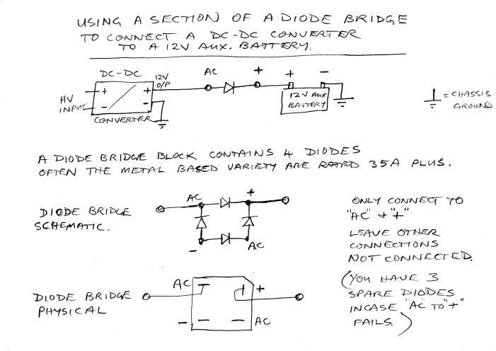
Download PDF here
|